Hotline :
0393 650 571
Hotline :
0393 650 571
Hotline :
0393 650 571

")
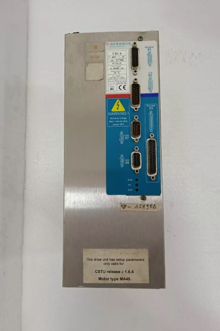
INFRANOR CD1-K 400 / 4.5 CD1K ( PCD1.19 )
INFRANOR CD1-K 400 / 4.5 CD1K ( PCD1.19 )
INFRANOR SERVO DRIVER CD1-K,U:400,I:
CD1-k Installation Guide, CANopen amplifier
This is a general manual describing a series of servo amplifiers having output capability suitable for driving AC brushless sinusoidal servo motors. Please see CD1-k User Guide for the operation of the amplifier (commissioning, configuration, ...). For the CANopen communication, see manual CD1-k – CANopen Communication Profile. Instructions for storage, use after storage, commissioning as well as all technical details require the MANDATORY reading of the manual before getting the amplifiers operational. Maintenance procedures should be attempted only by highly skilled technicians having good knowledge of electronics and servo systems with variable speed (EN 60204-1 standard) and using proper test equipment. The conformity with the standards and the "CE" approval is only valid if the items are installed according to the recommendations of the amplifier manuals. Connections are the user's responsibility if recommendations and drawings requirements are not met.
2.1 - GENERAL DESCRIPTION The CD1-k amplifier directly controls the motor torque and speed by means of the information provided by a high resolution position sensor (resolver or encoder). The sinusoidal current commutation based on this high resolution position sensor provides very smooth motor torque/force control. The CD1-k amplifier can be configured for the feedback of various position sensor types. The appropriate position sensor configuration is selectable by software and saved in the amplifier. - With a resolver sensor feedback, the motor absolute position value over one revolution is available and the servo motor can immediately be enabled after the amplifier power up. - With a "SinCos tracks" sensor which provides two analog Sin and Cos signals electrically compliant with the SinCos encoder signals and which period is equal to the motor pole pitch, the servo-motor can be immediately enabled after the powering of the drive. - With an absolute single-turn SinCos encoder feedback (Heidenhain ERN 1085 or compliant), the servo motor can also immediately be enabled after the amplifier power up. - With an incremental encoder only, a motor phasing procedure (Phasing) must be executed at each amplifier power up before the motor enabling. - With an incremental encoder + Hall Effect Sensors (HES) feedback, the motor phasing procedure is no more necessary and the servo motor can immediately be enabled after the amplifier power up. - With an absolute single-turn, multi-turn or linear encoder using the ENDAT or HIPERFACE communication protocols and fitted with incremental SinCos outputs, the servo-motor can also be immediately enabled after the powering of the drive.
Series CD1-k amplifiers have their own DC/DC converter to provide appropriate logic voltage to the modules. An auxiliary 24VDC +/- 15 % supply is generally available on all machines and supplies a DC/DC converter with all logic supplies required by the amplifier. The auxiliary supply allows to keep the logic board on, after the power supply has been switched off, in order to keep the position output and to avoid initializing the machine all over again. A 24 VDC battery supply with specific wiring allows to keep the position even after switching off the auxiliary 24 VDC supply. This wiring can be used for "absolute" operation with the CD1-k amplifier

")


")

")
")
")